VTK Surface LIC and Line Integral Convolution Revisions
Motivation
VTK's Surface LIC algorithm has proven itself an extremely useful tool and I regularly receive positive feedback from scientists on how it's helped to reveal new relationships in their simulation data. In the current implementation there are only a few basic controls for making adjustments to the step size, number of steps, and enabling and disabling a high pass filter and second LIC pass. These do not provide a great amount of control over the resulting image, as a result the efficacy of this implementation varies greatly across dataset, rendered image size, and choice of surface geometry. A tool such as VTK that is expected to process a wide variety of data under a wide variety of rendering conditions needs to provide more options and controls so that users can achieve good results in a variety of situations. This work identifies some issues in VTK's implementation and implements solutions to those issues. The goal here is not to replace the existing implementation but to add to it so that better result are attainable on a wider range of datasets and screen resolutions.
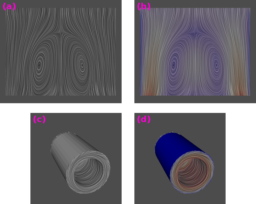
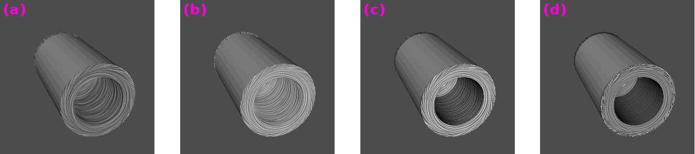
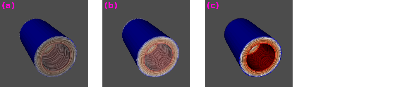
Figure 1:
Surface LIC visualization produced with the optimal settings available in ParaView 3.14. Two datasets are shown with and without scalar coloring. These frames illustrate some areas where there is room for improvment with the current surface LIC implementation. Details are presented in the text.
|
|
Some issues with either the surface LIC technique in general or with VTK's specific implementation are as follows:
- Low contrast and narrow dynamic range in the final image, producing dark and dull results. Figure 1.a illustrates this issue. Narrow dynamic range and low contrast are consequences of the convolution operation which tends to narrow the dynamic range and diminish contrast. This is made worse by the use of Gaussian noise because by definition Gaussian noise has most of it values concentrated near the mid gray value. This issue seems to affect planar surfaces more than curved ones.
- Dull or washed out look when scalar coloring is used. Figure 1.b illustrates this issue. In VTK's implementation scalar colors are blended with LIC values according to the following formula:
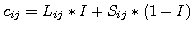 |
(1) |
where the indices  identify a specific fragment,
  is final RGB color,
  is LIC gray scale value,
  is the scalar RGB color, and
  is a constant ranging from 0 to 1, with a default of 0.8. Decreasing to obtain brighter colors diminishes the intensity of the LIC, and vise versa. When colors are bright the LIC is difficult to see. Currently, the best results are obtained by sacrificing on both fronts.
- No control over the streak characteristics which vary widely based on the input dataset, resolution of the final image, and choice of surface geometry. The streak characteristic in final image are influenced by many factors. One determining factor is the characteristics of the input noise texture itself. A noise texture that works well on one dataset at one screen resolution is likely to work poorly on another dataset or screen resolution. Figure 1.c illustrates this issue, wide streaking makes the interior of the cylindrical surface look lumpy. Note that this same noise texture is an excellent choice for the dataset shown in Figure 1.a. This issue may be specific to VTK's implementation which provides a single static noise texture, however, at least one author has claimed to provide ``optimal'' noise texture values which probably are only optimal for certain datasets.
- No control over fragment masking. Masked fragments are rendered invisible, revealing the scalar color shaded on the surface geometry at it's full intensity. This can be seen in figure 1.d. The issue here is that the masked fragments are much more intense than the LIC'ed fragments and thus distract from the presentation. There's also the issue of the choice of the masking criteria. In the current implementation fragments are masked when
 . However, most numerical simulations don't produce velocities that are exactly zero in stagnant regions. For example the dataset shown in figure 1 frames a, and b cannot be masked even though there are regions of very weak flow.
The following sections describe solutions to the above issues, and illustrate their efficacy using two test datasets that are included with VTK.
The remainder of the document describes solutions to the issues identified and described in the preceding section. These solutions are provided in addition to the current implementation. None of the current default values and options have been changed. All of the new features are disabled by default to maintain full backward compatibility. The following new features are provided:
- New Contrast and Color Contrast Enhancement
- The new contrast enhancement feature increases both dynamic range contrast while preserving patterns in the LIC without modifying scalar colors. See section 3.
- Enhanced scalar color shading
- A new mode has been added to the shader that shades surface geometry combining both LIC and scalar colors. The new shader produces bright colors without diminishing the visibility of the LIC. See section 5.
- Noise texture customization
- A new noise texture generator has been added. The noise textures produced are fully customizable over 9 degrees of freedom. See section 4.
- Fragment masking controls
- The new fragment masking provides controls over the color and intensity of masked fragments and their blending with scalars. Fragments are masked by threshold
 , where
  is a user specified threshold value, and
  are mask vectors. Masking vectors can be optionally projected onto the surface or passed through un-modified so that threshold is provided in the original vector units and matches scalar color shading. See section 6.
- Vector Normalization Control
- The new vector normalization control lets the user turn on and off normalization in the integrator. See section 7
New Contrast and Color Contrast Enhancement
The convolution process tends to decrease both contrast and dynamic range, often producing dark and dull results. Figure 1.a illustrates this issue. The narrowing of dynamic range and diminishing of contrast are consequences of the convolution operation which convolves a noise texture with a vector field. These reductions are made worse by the use of Gaussian noise because by definition centrally concentrates its values about a mid gray tone.
In order to counteract this, optional contrast enhancement stages have been added. The new stages increase the dynamic range and contrast without modifying the patterns that emerge from the LIC process or modifying the scalar colors. VTK's surface LIC implementation is provided by two classes, the vtkSurfaceLICPainter and vtkLineIntegralConvolution2D. The vtkSurfaceLICPainter, projects vectors, sets up noise texture, and passes control to the vtkLineIntegralConvolution2D to generate a LIC, after which it shades scalar colors combined with the generated LIC onto the surface geometry. Contrast enhancement stages have been added to both classes.
The pipeline employed by the vtkSurfaceLICPainter, including the new contrast enhancement stages, is shown in the following schematic:
         noise
           |
           [ PROJ LIC2D COLOR (CCE) ]
           |                        |
        vectors                  surface LIC
Where, the PROJ stage renders geometry, projecting vectors onto the surface, and the the screen; the LIC2D stage computes the LIC driving the vtkLineIntegralConvolution2D class; the COLOR stage combines LIC with scalar colors shading the surface geometry; and the CCE stage applies the new color contrast enhancement. Optional stages are enclosed in ().
In order to provide better interaction and faster response as parameters are varied during interactive exploration, each stage renders to a frame-buffer which is cached. This enables un-necessary stages to be skipped during interaction. For example, if an integrator parameter is modified then the geometry rendering and projection stage can be skipped. For large data this optimization can result in orders of magnitude speed up during interaction.
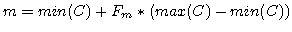
The color contrast enhancement stage is implemented with histogram stretching on the fragments lightness in the HSL color space.
 |
(2) |
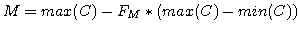
where, the indices identify a specific fragment, is the fragment's lightness in HSL space,  is the lightness to map to 0,
  is the lightness to map to 1. and take on minimum and maximum lightness over all fragments by default but may be individually adjusted by the following set of equations:
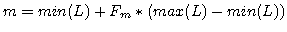 |
(3) |
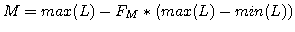 |
(4) |
where, are fragment lightness values and  and
and  are the adjustment factors that take on values between 0 and 1. When and are 0 minimum and maximum are lightness values are used. This is the default. Adjusting and above zero provides fine-tuning control over the saturation.
The pipeline employed in vtkLineIntegralConvolution2D, including the new contrast enhancement stages, is shown in the following schematic:
  noise texture
           |
           [ LIC ( ( CE ) HPF LIC ) ( AA ) ( CE ) ]
           |                                      |
  vector texture                              LIC'd image
Where LIC is the line integral convolution stage, HPF is a high-pass filter stage, CE is a contrast enhancement stage, and AA is an anti-aliasing stage. The optional stages are enclosed in (). Nested optional stages depend on the execution of their parent stage.
The contrast enhancement stages are implemented by histogram stretching of the gray scale colors in the LIC'ed image as follows:
 |
(5) |
where, the indices identify a specific fragment, is the fragment's gray scale color, is the gray scale color value to map to 0, is the gray scale color value to map to 1. When the contrast enhancement stage is applied on the input of the high-pass filter stage, and are always set to the minimum and maximum gray scale color of all fragments. In the final contrast enhancement stage and take on minimum and maximum gray scale colors by default but may be individually adjusted by the following set of equations:
 |
(6) |
 |
(7) |
where,
 , are all of the gray scale fragments in the LIC image and and are adjustment factors that take on values between 0 and 1. When and are 0 minimum and maximum are gray scale values are used. This is the default. Adjusting and above zero controls the saturation of normalization. This is useful, for example, if the brightness of pixels near the border dominate because these are convolved less because we can't integrate outside of the dataset.
Occasionally, often depending on the contrast and dynamic range and graininess of the noise texture, jagged or pixelated patterns may emerge in the LIC. These can be reduced by enabling the optional anti-aliasing pass.
The following images compare the new contrast enhancement feature to the optimal settings available in ParaView 3.14.
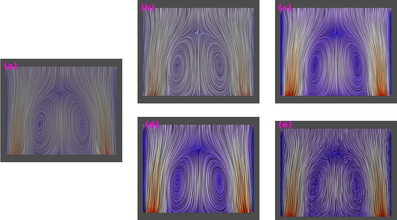
Figure 2:
Comparison of the new contrast enhancement(CE) feature applied to curved surface.
(a) Using optimal settings as of ParaView 3.14.
(b) With new contrast enhancement and the old scalar color shader enabled.
(c) With new contrast enhancement and new scalar color shader enabled.
(d) With new contrast enhancement and new scalar color shader, and vector normalization disabled.
|

|
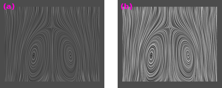
Figure 3:
Contrast enhancement(CE) applied to planar surface.
(a) Using optimal settings as of ParaView 3.14.
(b) Same settings but with new contrast enhancement feature enabled.
|
|
New Noise Texture Generator
The streak characteristics and look of the final LIC'ed image vary widely based on the input dataset, resolution of the final image, and choice of surface geometry. One important factor in determining the streaking characteristics and overall look of the final image are the characteristics of the input noise texture. The size of the noise pixels, the size of the noise texture, the contrast and dynamic range of the noise texture, all play a role in the look of the final image. Using the same noise texture produces markedly different results on different datasets and even on the same dataset at different screen resolutions. It's unlikely that a single noise texture will work well in all cases.
In order to provide more control over the streaking characteristics and general look of the final LIC image I have added customizable noise texture generator. The noise texture can be modified based on the following parameters:
- GenerateNoiseTexture
- Select between the default static noise texture or generate a custom noise texture using the following parameters.
- NoiseType
- Select between Gaussian, uniformly distributed noise, or Perlin noise.
- NoiseTextureSize
- Select the number of pixels in a side of the square noise texture.
- NoiseGrainSize
- Select the number of pixels each side of the square noise value spans.
- MinNoiseValue
- Set the lowest color in the noise texture, the default, 0, is black.
- MaxNoisevalue
- Set the highest color in the noise texture, the default, 1, is white.
- NumberOfNoiseLevels
- Set the number of noise colors.
- ImpulseNoiseProbability
- Impulse noise noise can be generated with a probability less than 1.
- ImpulseNoiseBackgroundColor
- The color to use for un-touched pixels.
- NoiseGeneratorSeed
- Modify the seed value of the random number generators.
Changing the noise texture gives one greater control over the look of the final image. By default the original static 200x200 noise texture (see VTKData/Data/Data/noise.png) is used.
The following figures illustrate some of the features of the new noise texture generator.
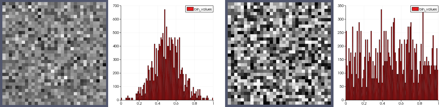
Figure 4:
Custom noise texture generator example. Two noise textures are shown, the first contains Gaussian noise, the second contains uniform noise.
|
|
Figure 5:
Custom noise texture generator example. Two noise textures containing Gaussian noise are shown, the first with a grain size 1, the second with a grain size of 4.
|

|
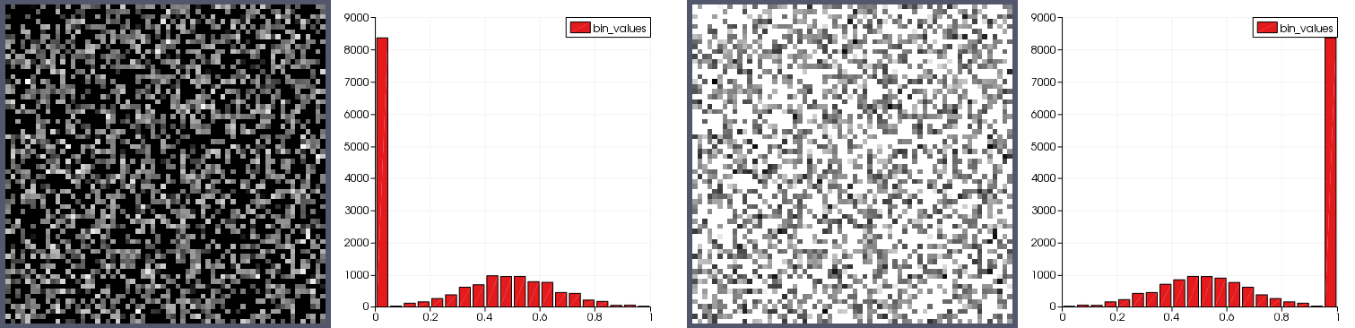
Figure 6:
Custom noise texture generator example. Two noise textures containing Gaussian impulse noise. The first has a background color of black and the second white.
|
|
The following images compare the use of a custom noise texture with the static 200x200 noise texture and optimal settings available in ParaView 3.14.
Figure 7:
Comparison of new color enhancement applied to test a curved surface.
(a) Using optimal settings as of ParaView 3.14.
(b) A contrast enhanced LIC using a custom noise texture shaded with the old shading technique described by equation 10.
(c) A contrast enhanced LIC using a custom noise texture shaded with the new shading technique described by equation 9.
(d) A contrast enhanced LIC using a custom noise texture shaded with the new shading technique described by equation 9 and vector normalization disabled.
|
|
New Scalar Color Shader
The current approach for shading the LIC'ed image with scalar colors blends the scalar colors with the LIC according to
|
(8) |
where the indices identify a specific fragment, is final RGB color, is LIC gray scale value, is the scalar RGB color, and is a constant ranging from 0 to 1, with a default of 0.8. Decreasing to obtain brighter colors diminishes the intensity of the LIC, and vise versa. When colors are bright the LIC is difficult to see. Currently, the best results are obtained by sacrificing on both fronts.
The purpose of the new scalar color shader is to provide both bright and intense scalar colors without diminishing the visibility of the LIC itself. The shader is implemented by the following equation:
 |
(9) |
where the indices identify a specific fragment, is final RGB color, is LIC gray scale intensity, is the scalar RGB color, and  is a biasing parameter, typically 0, that may be used for fine tuning. When
  , the typical case, colors are transfered directly to the final image where the LIC is 1, and a linearly scaled transfer of scalar colors where LIC gray scale color is less than one down to 0, where the final color is black. The bias parameter may be set to small positiver or negative values between -1 and 1 to increase or decrease LIC values uniformly resulting in brighter or darker images. When
  final fragment colors, , are clamped such that
 .
.
The following images compare new color enhancement feature to the optimal settings available in ParaView 3.14.
Figure 8:
Comparison of new color enhancement applied to test a curved surface.
(a) Using optimal settings as of ParaView 3.14.
(b) With custom noise texture, new contrast enhancement, and the old scalar color shader enabled.
(c) With custom noise texture, new contrast enhancement and new scalar color shader enabled.
|
|
Figure 9:
Comparison of new color enhancement applied to test a planar surface.
(a) Using optimal settings as of ParaView 3.14.
(b) With custom noise texture (grain size=1), new contrast enhancement, and the old scalar color shader enabled.
(c) With custom noise texture (grain size=1), new contrast enhancement and new scalar color shader enabled.
(e) With custom noise texture (grain size=2), new contrast enhancement and new scalar color shader enabled.
(d) With custom noise texture (grain size=2), new contrast enhancement and new scalar color shader enabled, and vector normalization disabled.
|
|
Improved Fragment Masking
Currently the criteria for masking fragments is that all vector components must be identically zero. This doesn't work for many numerical simulations where stagnant flow is not identically zero due to numerical rounding. For example, stagnate flow might be where
 . Also, the lack of control over the color characteristics of the masked fragments result in masked fragments looking drastically different than the LIC'ed fragments. This is illustrated in figure 1.d where all fragments on the outer walls have been masked , the masked fragments are much brighter than the the LIC'ed fragments.
New fragment masking implementation makes use of a user specified threshold value below which fragments are masked. The masking test may be applied either to the original vectors or the surface projected vectors. By applying the test to the original vectors the masked fragments will match scalar colors when coloring by  .
.
Fragments where  are masked. The fragment masking implementation provides control over the intensity and color of the masked fragments via the following equation:
 |
(10) |
where the indices identify a specific fragment, is final RGB color, is the RGB mask color, is the scalar RGB color, and is the mask color intensity. This allows one control over the masking process so that masked fragments may be: highlighted (by setting a unique mask color and mask intensity > 0), made invisible with and without passing the un-convolved noise texture (by setting mask intensity 0), or made to show the scalar color at a similar level of intensity as the LIC (mask intensity > 0).
The following images compare new color enhancement feature to the optimal settings available in ParaView 3.14.
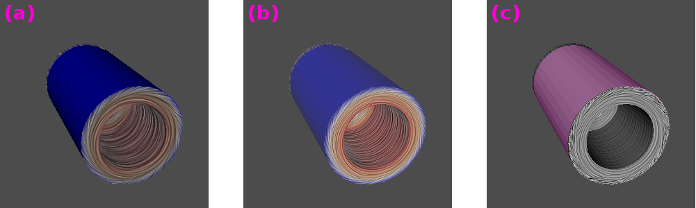
Figure 10:
Comparison of new fragment masking features applied to test a curved surface.
(a) Using optimal settings as of ParaView 3.14.
(b) With new fragment masking (I=0.2, M=white), custom noise texture, new contrast enhancement, and the old scalar color shader enabled.
(c) With new fragment masking (I=0.8, M=pink), custom noise texture, new contrast enhancement and new scalar color shader enabled.
|
|
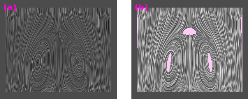
Figure 11:
Comparison of new fragment masking features applied to test a curved surface.
(a) Using optimal settings as of ParaView 3.14.
(c) With new fragment masking (I=0.8, M=pink), custom noise texture, new contrast enhancement and new scalar color shader enabled.
|
|
Vector Field Normalization
Normalizing vectors during integration can highlight critical points in the flow. However, it can alter the relationships of flow features making weak features prominent and strong features less so. When normalized(the default) the input vector field is normalized during integration, and each integration occurs over the same arc-length. When not set each integration occurs over an arc length proportional to the field magnitude as is customary in traditional numerical methods. See, "Imaging Vector Fields Using Line Integral Convolution" for an example where normalization is used. See, "Image Space Based Visualization of Unsteady Flow on Surfaces" for an example of where no normalization is used. Both approaches are valid and useful, the new feature allows for the selection of one or the other.
A comparison of the LIC with vectors normalized and not normalized is shown in Figures 2.c, 9.e, 7.d, 11.c.
This work identified several issues of either surface LIC algorithm or VTK's implementation, provided solutions to these issues, and illustrated the efficacy of the new features on two of VTK's test datasets. The proposed solutions extend VTK's functionality providing users with more options without changing current defaults and behavior.
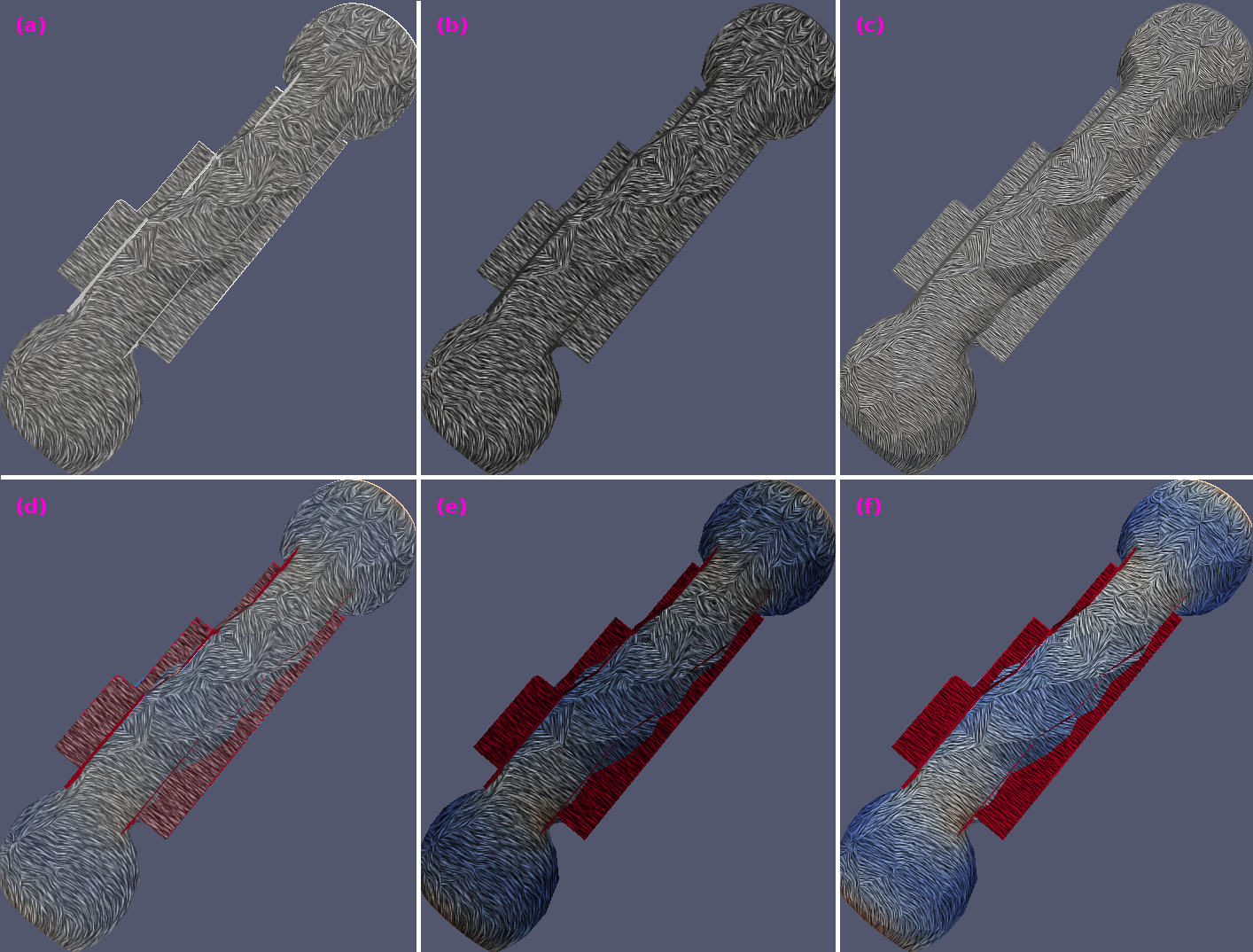
Figure 12:
New features are applied to a Ensight Multi-Block dataset
(a) Old scalar color shader, solid color.
(b) New scalar color shader, solid color.
(c) New scalar color shader, a custom noise texture (Gaussian, grain size 1), and contrast enhancement.
(d) Old scalar color shader, color by scalars.
(e) New scalar color shader, color by scalars.
(f) New scalar color shader, color by scalars, a custom noise texture (Perlin, grain size 4), and contrast enhancement.
|
|
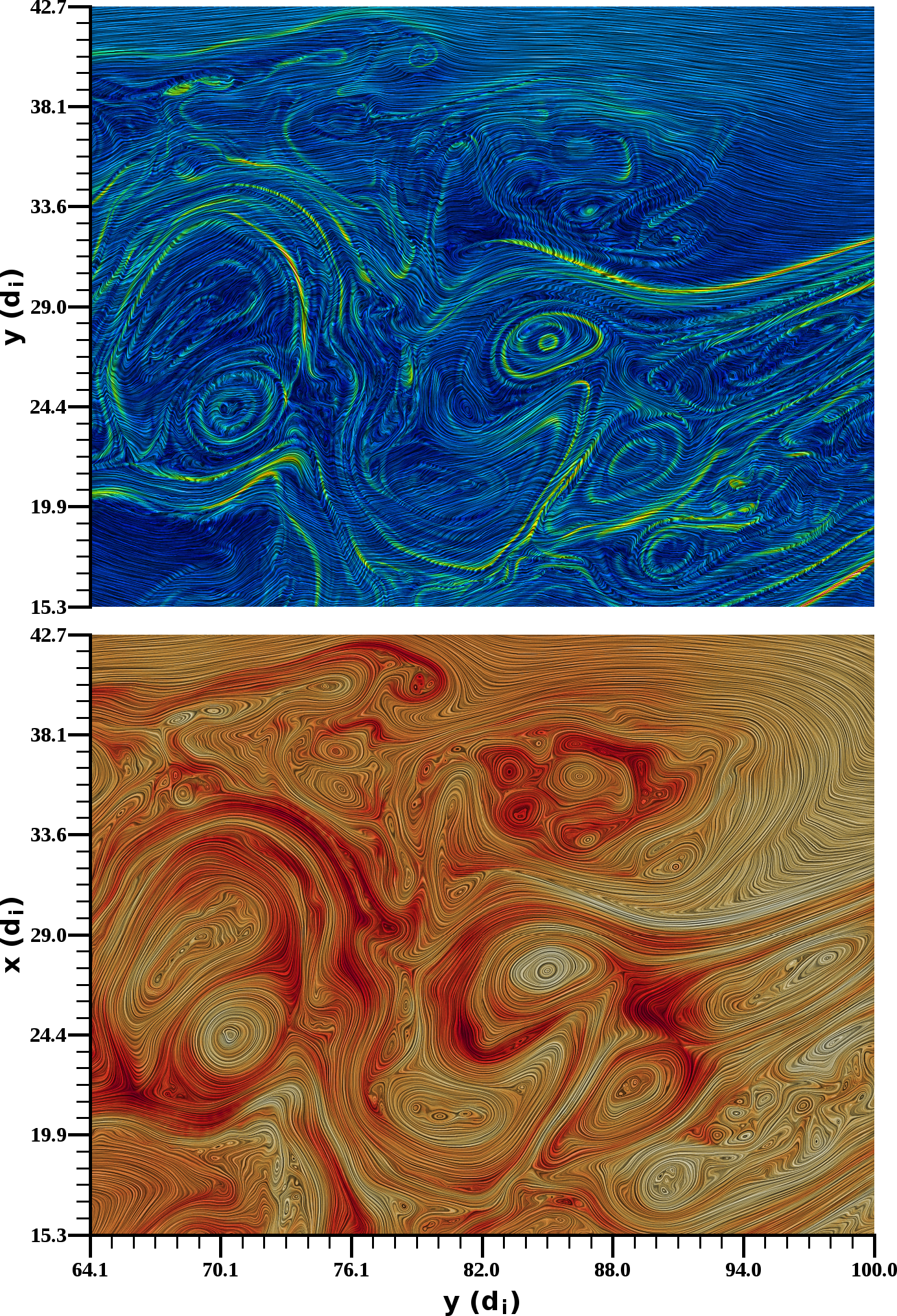
Figure 13:
New features applied to plasma simulation data. Lower panel: LIC of magnetic field colored by field magnitude. Upper panel LIC of electron velocity, colored by velocity magnitude.
|
|
VTK Surface LIC and Line Integral Convolution Revisions
This document was generated using the
LaTeX2HTML translator Version 2008 (1.71)
Copyright © 1993, 1994, 1995, 1996,
Nikos Drakos,
Computer Based Learning Unit, University of Leeds.
Copyright © 1997, 1998, 1999,
Ross Moore,
Mathematics Department, Macquarie University, Sydney.
The command line arguments were:
latex2html -split 0 -no_navigation -white -no_math -no_antialias_text vtk-surface-lic-revisions.tex
The translation was initiated by Burlen Loring on 2012-11-18
Burlen Loring
2012-11-18